| Nick Shubin | ||||
| Home | Articles | Photos | Publications | Site Map |
Nick Shubin
August 10, 2014
This article explains how to create a 3D model of sloping terrain in the SketchUp software for using it in your Live Interior 3D project. Of course, you can use the created object in any 3D software which can import SketchUp files. One more program needed is graphic software with Free Hand or Spline drawing tool which lets you do some very basic drawing and save it to a graphic file.
Some steps require certain experience in using SketchUp. In case of difficulties, refer to tutorials dedicated to respective features.
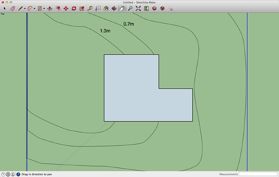
1. Create a topographic map where closed contours display points with the same elevation. Indicate the elevation near each contour. Add the outline of the house and any important objects such as shed, garden or driveway if they should appear on the piece of land you are going to model. Save to a PDF file (PNG or JPEG would work as well).
You can also make use of a professionally created topographic map if it is available.
It is important that you know exactly the total size of the map. This is needed to scale it properly in SketchUp. The sample map is 40 meters per each side.
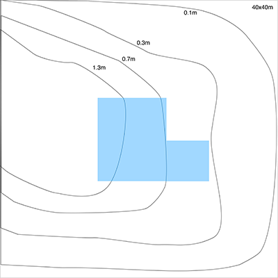
Don't make the map too detailed. Contours shouldn't be too curvy. Don't add more than 4-5 of them. If you are going to model a smooth slope, one contour would be enough just to indicate the highest part of your model.
2. Open a new project in SketchUp. The further steps will be completed in this program. Choose View > Standard Views > Top (Cmd-1).
3. Open the project setting using Window > Model Info (Cmd-Shift-I). In the Unit section, set up the measurement units. Since the topographic map created at step 1 uses meters, we select "Decimal and Meters" for Format, and keep the default precision. Your settings may be different, but remember that to successfully fit the created terrain into your Live Interior project, both should have the proper scale.
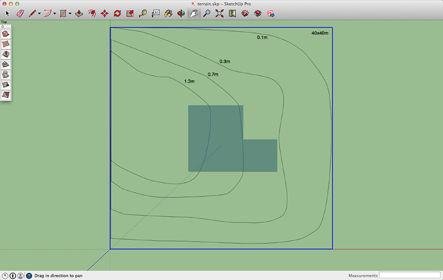
4. Import your topographic map using the File > Import menu command. Choose the "As Image" option. Click at zero point to set the origin. Then type the dimensions into the Measurements box. For 40 by 40 meters, we should type "40,40" and press the Return key.
Using the Zoom and Pan tools, fit the imported image to the screen.
Move the image by 0.6m along the blue axis. This is not necessary but useful to easily delete it later.
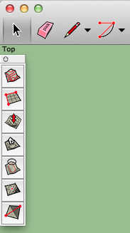
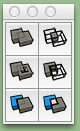
5. Select View > Tool Palettes > Sandbox to bring up the Sandbox tools.
6. We are about to add a customizable surface (so called Sandbox). The Sandbox comprises of a grid whose Grid Spacing property defines how detailed the future terrain model can be. Making the terrain too much detailed can slow down rendering of your Live Interior project. Since the terrain is not the most important part of it, it is recommended to make it as less detailed as possible.
In the Sandbox panel, activate the From Scratch tool. The default Grid Spacing is 1m. For the sample project 2m would be enough. We type "2" and hit Return. Click at zero point and drag the cursor horizontally. Type "40" (for 40m) and hit Return. Then drag vertically, type "40" again and press the Return key.
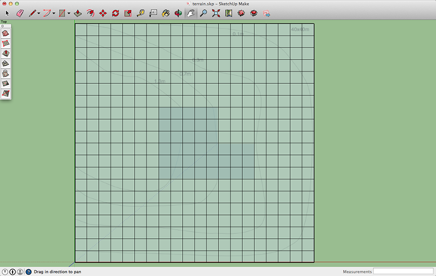
Make sure that the Sandbox grid is placed exactly above the image but at about 0.6m distance vertically.
7. To be able to see the topographic map through the grid, select View > Face Style > X-Ray.
8. Find out the increments between the levels indicated on the map. The levels are: 0m, 0.1m, 0.3m, 0.7m and 1.3m. Correspondingly, the increments are: 0.1m, 0.2m, 0.4m and 0.6m.
9. Now we are ready to elevate the ground level. We'll raise the bigger contour by 0.1m, then the following smaller one by 0.2m (see the increments list) and so on.
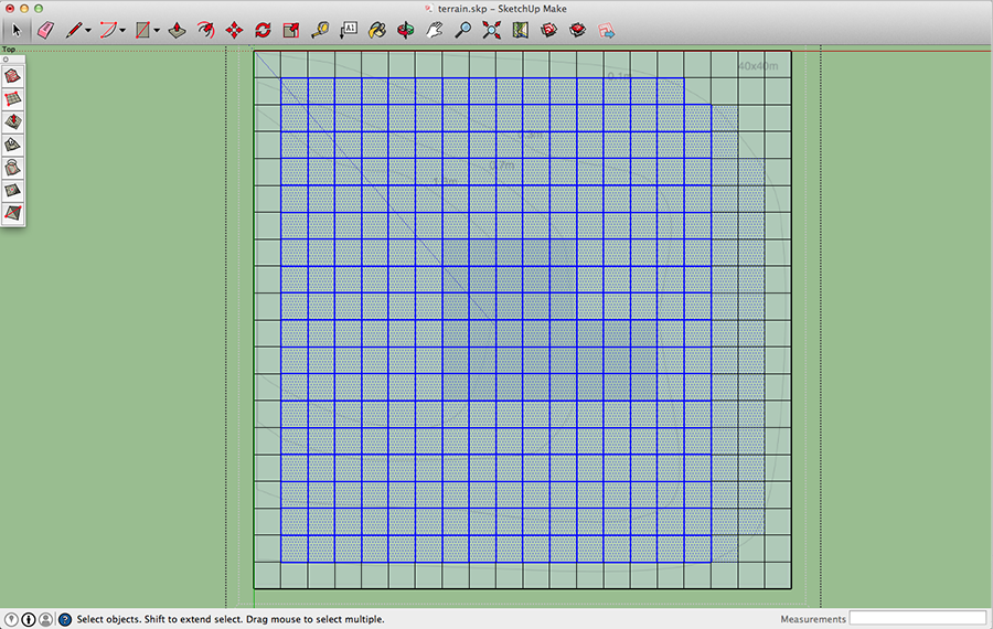
9.1. Right-click on the grid and select the Explode command.
9.2. Using the selection frame, select cells that are inside the biggest contour. If you cannot select some of them with the frame, or have selected those that outside the contour, add or remove cells from the selection by Shift-clicking on them. IMPORTANT: never select cells along the edge of the grid to keep the grid outline unchanged.
9.3. Click on Smoove tool in the Sandbox panel.
9.4. Set the Radius to 1m by hitting "1" and Return keys. There is no need to repeat this every time. The larger radius you set, the smoother slopes you'll get around the selected area.
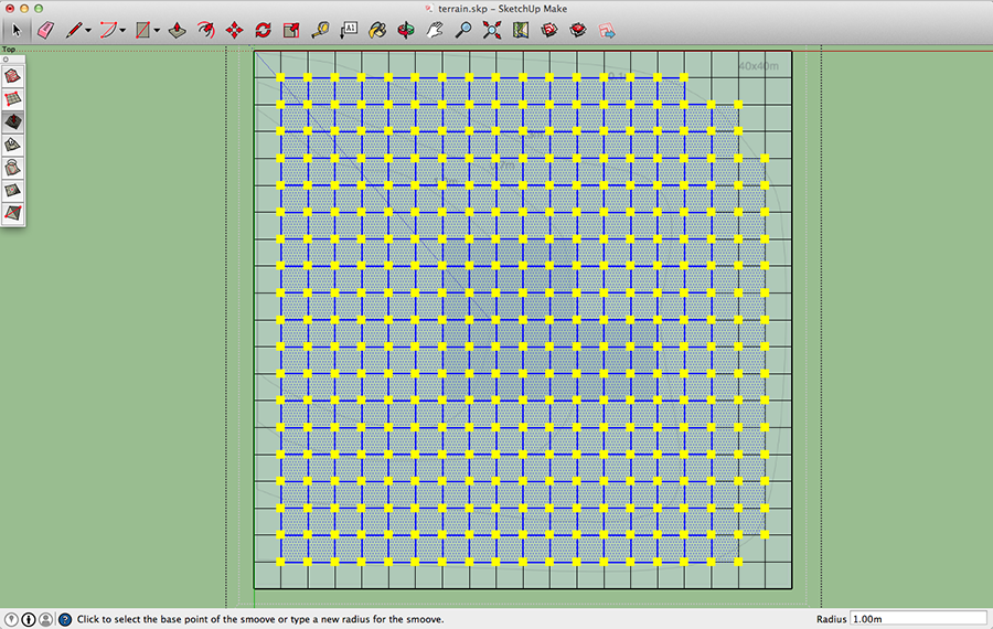
9.5. Click on any of yellow handles.
9.6. Set the Offset to 0.1m (the first increment) by typing "0.1" and hitting Return.
9.7. Activate the Select tool in the toolbar and then click on empty space to deselect everything.
9.8. Repeat 9.3-9.7 with the rest contours proceeding from the biggest to the smallest one.
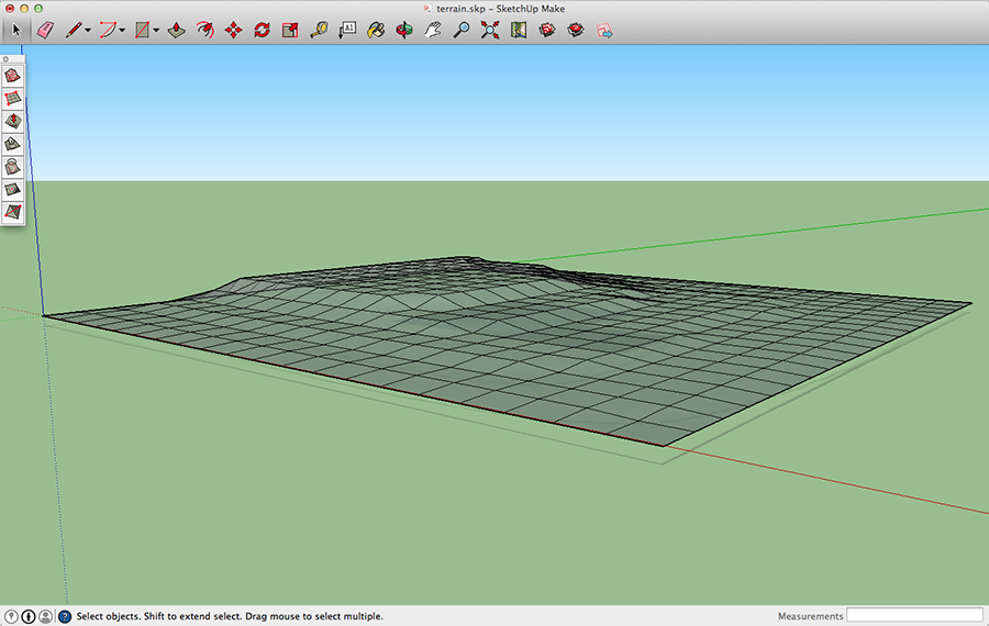
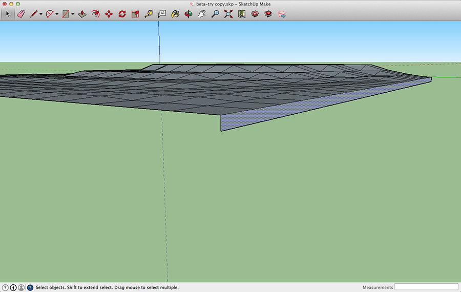
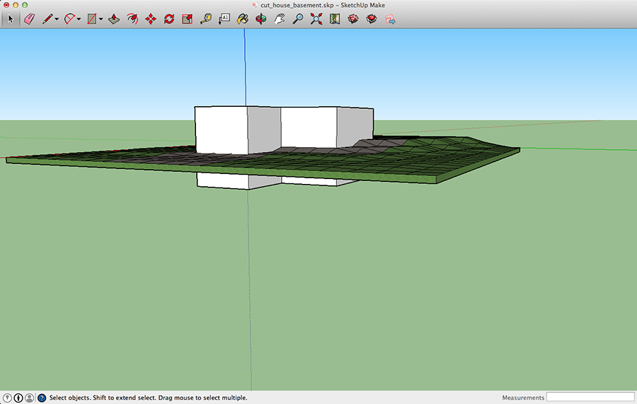
To preview the result, look at the model from a side.
10. Turn the zero thickness surface into a 3D object with some body by giving it a boxy look in order to use it in Live Interior. To do this, add vertical rectangles at three sides and the bottom. The last side will appear automatically. The hight of the base should be about 0.5m.
11. Applying textures.
If the piece of land you model includes different types of pavement, soil, lawn or their combination, apply different textures to the respective areas. You need to do this in SketchUp before importing your model to Live Interior 3D. The latter lets you change any texture within the space it already takes, but it cannot apply the second texture to a part of a single-texture area.
If the same texture should cover the whole model, proceed to the following step.
If your model is a group or component, right-click on it and select Explode.
To apply a new texture to a part of the model, select the corresponding faces using the selection frame or by Shift-clicking on each of them. Then activate the Paint Bucket tool and choose a texture.
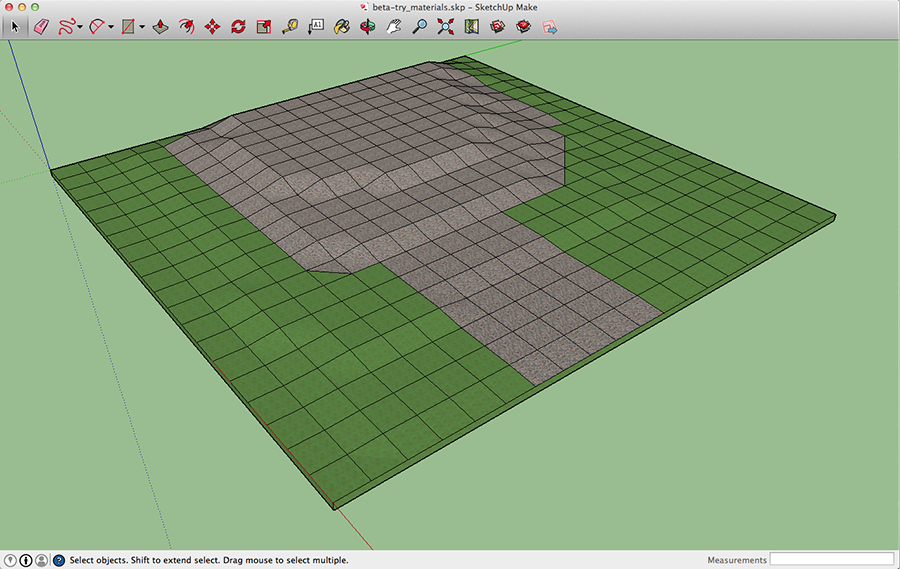
The smallest part of the surface you can paint individually is a grid cell created with the Sandbox tools. The grid may not coincide with your driveway or garden path. To fix this, cut certain cells into parts using the drawing tools. For instance, if you draw a diagonal, you'll be able to apply different textures to each of created triangles.
12. Delete the topographic map. Then save your model.
13. Importing the terrain to Live Interior 3D. From now, let's call the imported terrain "sloped terrain" to distinguish it from the default Terrain object.
Simply drag and drop the *.skp file onto the 2D view window in Live Interior 3D. Using the Inspector, make sure that the sloped terrain has the proper scale (40m by 40m in our example).
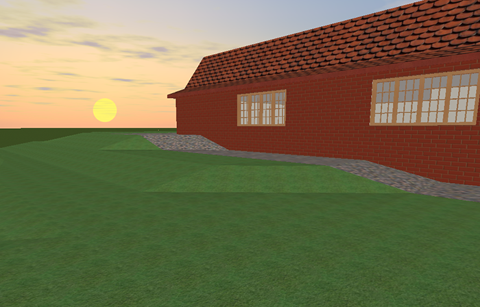
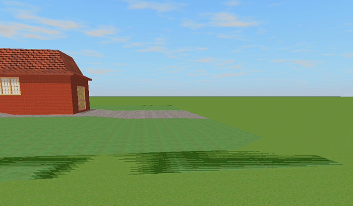
14. Set the elevation for the sloped terrain. At step 10, we added a 0.5m base. Now we need to lower it under the ground. Set the Elevation parameter in the Inspector to "-0.5". Then, in the 3D view, walk around near the sloped terrain border and search for graphical artifacts as in the picture below. Sometimes you need to rotate to see problem. If they are, raise the object by 0.01m (or click once on the stepper next to the edit box).
15. The sloped terrain is almost finished.
However there is one important thing to check out. Go inside the house and check the ground floor and basement (if you have it). See if you've got a pile of stones, soil of grass inside.
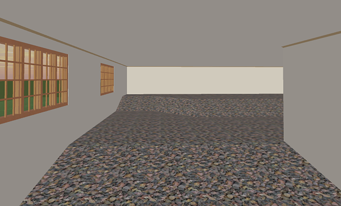
This is how Live Interior 3D treats objects when they intersect one another. The program cannot automatically cut out the unnecessary part, hence sloped terrain can be visible inside the house. You can remove it by editing the object in SketchUp. The idea of what to do is given in the next step.
If your building has no basement, and the sloping terrain is not much higher than the ground floor level, then there can be another solution. Simply elevate the floor until the portion of the sloping terrain visible inside disappears. To do this, increase the Elevation and Foundation parameters in the Building tab of the Inspector by the same amount. Then lower the sloping terrain by the same value to restore its elevation in relation to the default Terrain. If you succeeded, go to the step 17. Otherwise, undo and proceed to 16.
16. Removing soil under the house.
There are two ways to do this. The first is based on use of the Solid tools which are available in SketchUp during the trial period and in the Pro version. The following steps explain this method. The second way is editing the model by adding or removing faces. All needed tools are available in any version of SketchUp including the free one. The second method requires some experience in 3D model editing, and it won't be discussed here because of its complexity.
16.1. Open your *.skp file in SketchUp. Using the Edit > Edit in Trimble SketchUp command from the Live Interior 3D main menu is not recommended. Make sure that the model has been converted into a component.
16.2. Create a new SketchUp document.
16.3. Import the topographic map again as we need to see the outline of the house. Do this the same way as before.
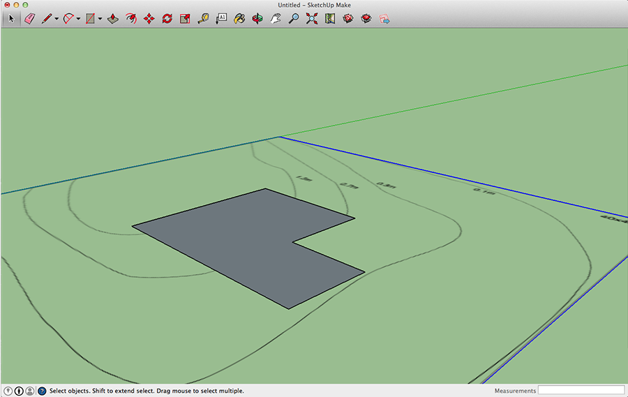
16.4. Using the Line tool, draw the outline of the building. As soon as you close the shape, a face will be created.
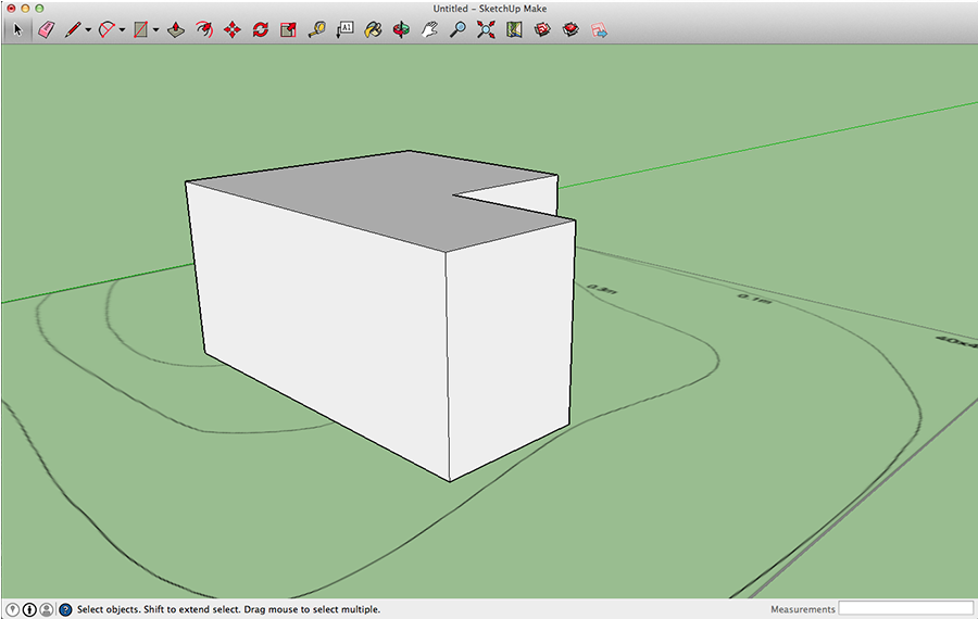
16.5. Switch to the isometric view by choosing Camera > Standard Views > Iso (Cmd-7).
16.6. Use the Push/Pull tool to extend the face upwards and create a 3D shape. The hight should be about doubled hight of the terrain model, just by eye.
16.7. Activate the Select tool. Select all (Cmd-A) and Shift-click on the map in order to select everything but the map. Right-click on the 3D shape and select Make Component. Accept the default settings.
16.8. Zoom out to fit the topographic map into the window. Select the map. Activate the Move tool, and holding down the Up Arrow key, move the map exactly upwards to the middle of the shape hight. One of map corners must remain exactly on the blue axis.
16.9. Copy all and paste to the document with the terrain. Make sure that the origin coincides with the blue axes what makes the map to be placed exactly above the terrain.
Delete the terrain map.
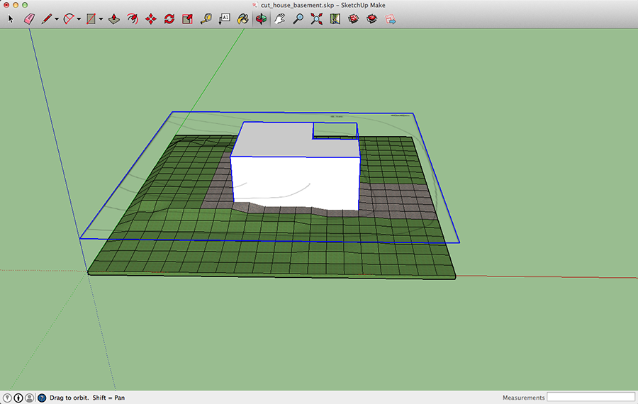
16.10. Make the 3D shape sink through the terrain. The two objects should intersect.
16.11. Select View > Tool Palettes > Solid Tools to bring up a floating panel.
16.12. Activate the Subtract tool. Click on the 3D shape to indicate the Component 1 (what to remove), then click on the terrain as the Component 2.
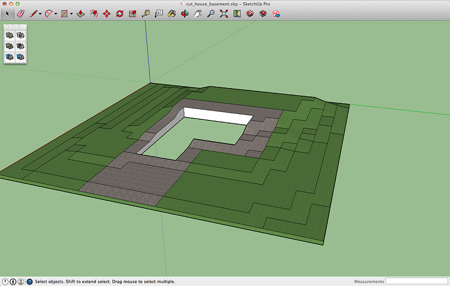
That simple.
There is a chance that you aren't able to select one of the components because it is not solid. Basically this can mean that your component has unnecessary faces or edges hiding inside, and you need to find and delete them. Also you could have forgotten to delete the topographic map. If the map is inside the component, delete it. Unfortunately SketchUp won't give you any clue. You have to check the model manually.
16.13. In the Live Interior project, replace the sloping terrain with its new version. Then make sure that it is perfectly aligned with the building. If it isn't, you'll see small parts of the sloping terrain on the ground floor or basement. To fix this, open the 2D and 3D views together. Move the sloping terrain on the floor plan using the arrow keys and control the result in 3D.
17. If needed, apply the final textures to the sloping terrain.
© 2016 Nick Shubin. All rights reserved.